
Directional Coupler - 5G - 698-4000 MHz
Directional Couplers are passive RF components used to split, combine, and monitor RF signals in microwave and communication systems while maintaining controlled signal flow and impedance matching. These components are widely used in telecom infrastructure, RF testing, radar systems, satellite communication, DAS networks, and microwave transmission applications where accurate signal sampling and power distribution are essential.
At SRFS Teleinfra, we offer high-performance directional couplers designed for reliable RF signal distribution, low insertion loss, excellent directivity, and stable electrical performance across a wide frequency range. Our directional couplers are suitable for telecom, 4G/5G communication systems, RF laboratories, wireless infrastructure, and microwave applications.
Our RF directional couplers are manufactured using precision-engineered materials and advanced RF technology to ensure low VSWR, high isolation, accurate coupling values, and dependable signal monitoring performance even in demanding RF environments.
All our directional couplers are manufactured in India using quality-tested raw materials and strict quality control standards, ensuring reliable operation, long service life, and cost-effective RF solutions for telecom and microwave industries across the country.
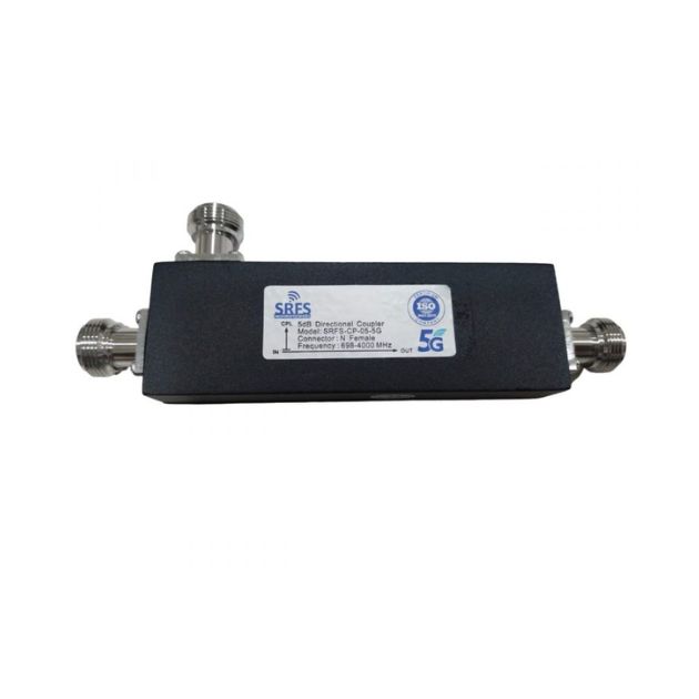
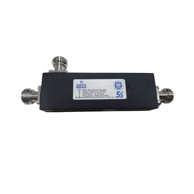
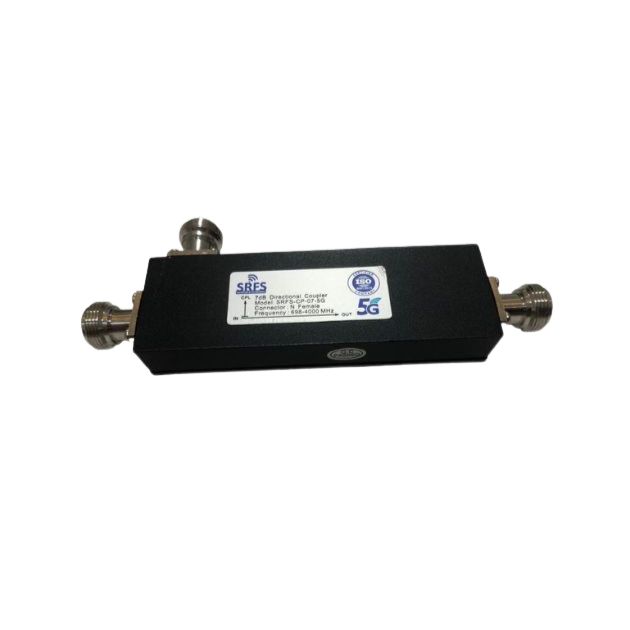
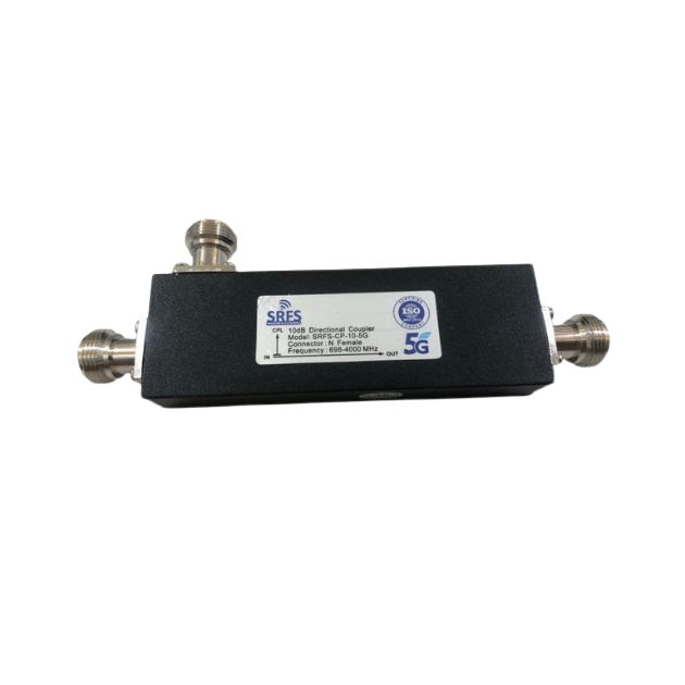
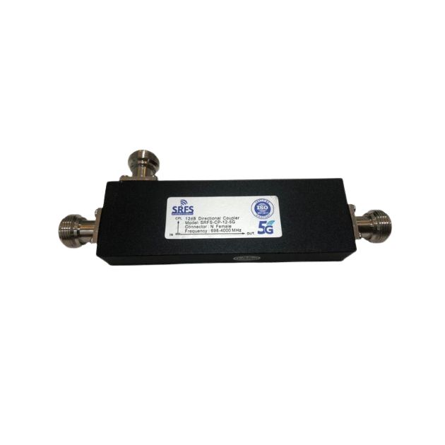
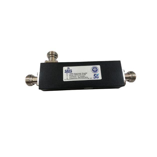
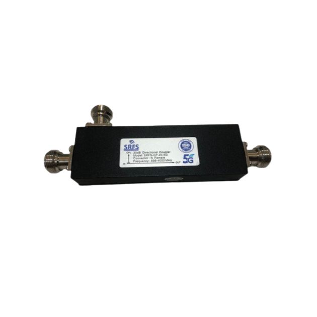
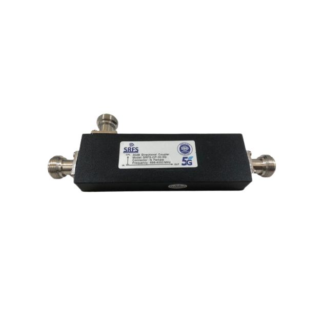
What is a Directional Coupler?
A directional coupler is an RF device used to couple a defined amount of electromagnetic power from a transmission line to another port while minimizing interference with the main signal path. It enables signal monitoring, power measurement, signal splitting, and RF signal distribution in communication systems.
Directional couplers are commonly used in RF communication systems to sample signals without interrupting the main transmission line, making them essential in RF testing, microwave communication, and telecom applications.
Types of Directional Couplers
3 dB Directional Coupler
A 3 dB directional coupler equally splits the input signal power between the output ports. It is widely used in RF signal distribution, power combining, and balanced communication systems where equal signal division is required.
6 dB Directional Coupler
A 6 dB directional coupler provides moderate signal coupling while maintaining low insertion loss in the main transmission line. These couplers are commonly used in RF monitoring and signal sampling applications.
10 dB Directional Coupler
10 dB directional couplers extract a smaller portion of the RF signal for monitoring and measurement purposes while allowing most of the power to continue through the main line. They are widely used in telecom and RF testing systems.
15 dB Directional Coupler
A 15 dB directional coupler is designed for controlled signal sampling with minimal impact on the primary RF transmission path. These couplers are suitable for wireless communication and microwave applications.
20 dB Directional Coupler
20 dB directional couplers are commonly used for signal monitoring, RF measurement, and power detection applications where only a small amount of signal power needs to be sampled.
30 dB Directional Coupler
A 30 dB directional coupler provides very low signal coupling and is ideal for high-power RF systems, sensitive monitoring applications, and precision microwave communication systems.
Technical Specifications of Directional Couplers
Electrical Specifications
- Frequency Range: 600 MHz to 6000 MHz
- Coupling Values: 3 dB, 6 dB, 10 dB, 20 dB, 30 dB
- Impedance: 50 Ohm
- VSWR: ≤ 1.25:1
- Low Insertion Loss
- High Isolation & Directivity
Mechanical Specifications
- Connector Type: N Female / DIN Female / SMA
- Rugged Metal Housing
- Compact RF Design
- Indoor & Outdoor Installation Support
Environmental Specifications
- Operating Temperature: -40°C to +85°C
- Corrosion Resistant Construction
- High Mechanical Durability
- Suitable for Telecom & RF Environments
Applications of Directional Couplers
- Telecom and BTS installations
- 4G / 5G wireless communication systems
- RF signal monitoring applications
- Microwave and radar systems
- DAS and in-building coverage systems
- RF testing and laboratory setups
- Satellite communication systems
- Power measurement and signal sampling
Directional couplers are widely used for signal distribution, RF monitoring, impedance matching, and maintaining stable signal transmission in communication systems.
Advantages of Directional Couplers
- Accurate RF signal sampling
- Low insertion loss and low VSWR
- High isolation and excellent directivity
- Stable RF performance across wide frequencies
- Compact and durable RF design
- Suitable for telecom and microwave applications
Product Specifications
| Directional Coupler Type | Impedance | Frequency Range | Application |
|---|---|---|---|
| 5dB Directional Coupler | 50 Ohm | 698–4000 MHz | RF Signal Distribution & Monitoring |
| 6dB Directional Coupler | 50 Ohm | 698–4000 MHz | Wireless Communication Systems |
| 7dB Directional Coupler | 50 Ohm | 698–4000 MHz | Telecom & DAS Applications |
| 10dB Directional Coupler | 50 Ohm | 698–4000 MHz | RF Testing & Signal Sampling |
| 12dB Directional Coupler | 50 Ohm | 698–4000 MHz | Microwave & RF Communication Systems |
| 30dB Directional Coupler | 50 Ohm | 698–4000 MHz | High Isolation RF Monitoring Applications |
Why Choose us
Precision RF Engineering
Our directional couplers are designed using advanced RF technology for stable signal distribution and accurate coupling performance.
Wide Frequency Support
Suitable for telecom, microwave, DAS, and RF communication applications across broad frequency ranges.
Low VSWR & Excellent Signal Stability
Engineered for minimal signal reflection, low insertion loss, and excellent isolation performance.
Durable Construction
Manufactured using premium-quality materials for reliable long-term operation in indoor and outdoor environments.
Frequently Asked Questions
A directional coupler is used to split, monitor, or sample RF signals in communication and microwave systems.
It couples a specific amount of RF power from the main transmission line while maintaining signal flow and impedance matching.
Most RF directional couplers are designed with standard 50 Ohm impedance.
Directional couplers are available for frequencies ranging from MHz bands up to microwave GHz ranges.
Coupling value indicates how much signal power is extracted from the main line, commonly available in 3 dB, 6 dB, 10 dB, and 20 dB values.
VSWR indicates impedance matching quality. Lower VSWR helps reduce signal reflection and improves RF performance.
They are used in telecom systems, RF testing laboratories, microwave communication, DAS systems, and radar applications.
Insertion loss refers to the signal power lost when the coupler is inserted into an RF transmission line.
High directivity improves signal isolation and ensures accurate RF signal sampling and monitoring.
Yes, directional couplers are widely used in 4G, 5G, microwave, and advanced telecom communication systems.